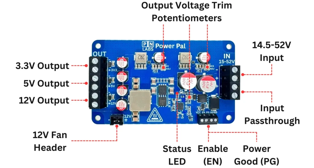
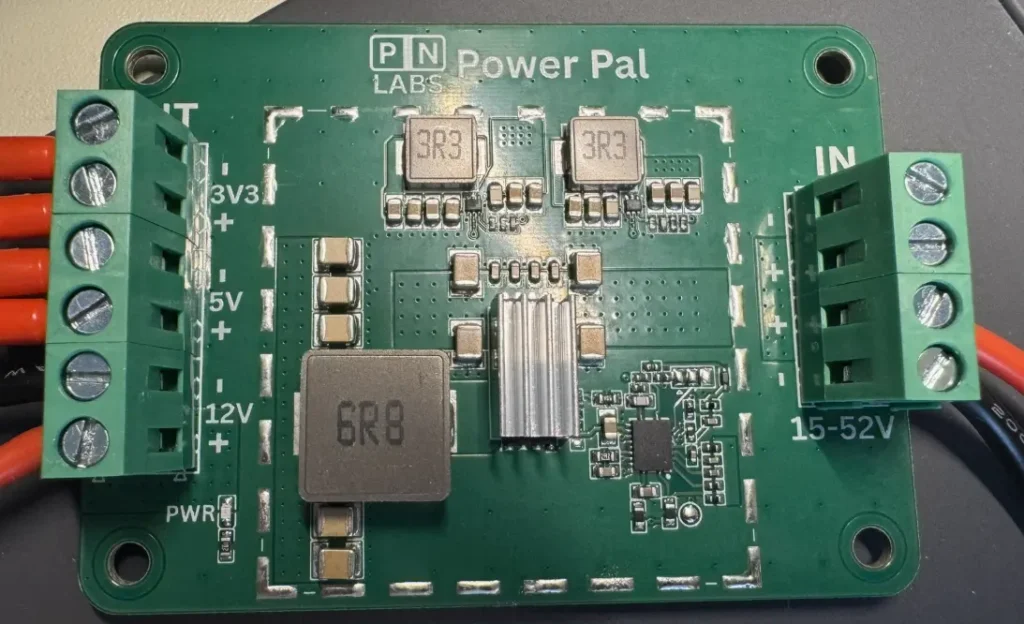
14.5–52 V Input | 12 V at 16 A | 5 V at 6 A | 3.3 V at 6 A
This project is a high power multi output synchronous buck regulator designed to deliver a clean and stable 12 V rail along with secondary 5 V and 3.3 V logic rails. It accepts a wide 14.5–52 V input range and outputs up to 240 W total power, making it suitable for applications that need both power delivery and sensitive digital rails. The design uses an LM5145 based synchronous stage for 12 V, feeding two downstream high efficiency buck converters for the lower voltage rails. The system includes reverse polarity protection, TVS surge suppression, UVLO cutoff, and a high-speed layout optimized for low EMI and fast transient response.
Design Evolution
The first revision focused on basic functionality: a straightforward LM5145 synchronous buck layout with modest output filtering. While functional, it showed measurable switch node ringing, high frequency noise, thermal issues and transient droop on the lower voltage rails.
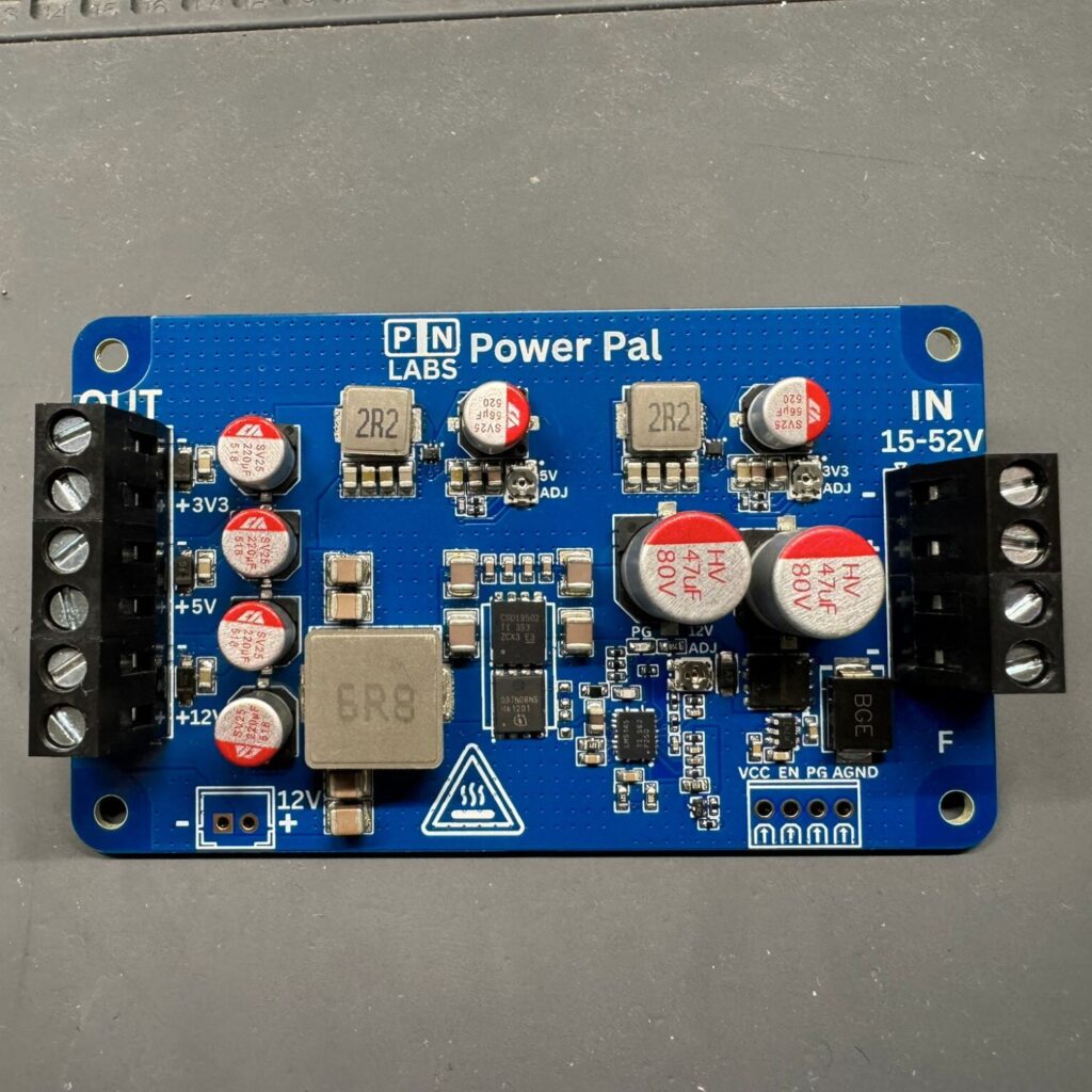
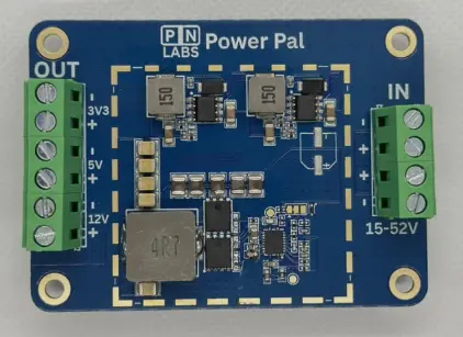
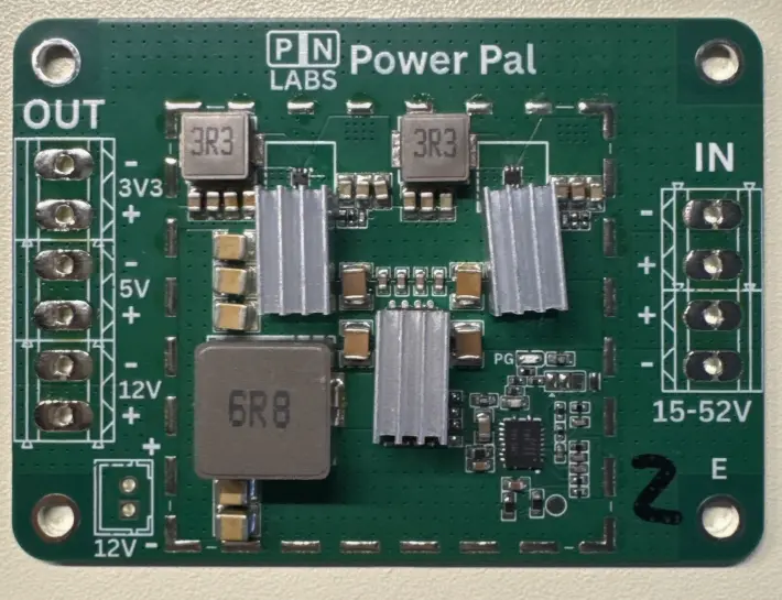
The final revision features a thoroughly optimized layout with a much tighter switch node loop, improved MOSFET selection to enable a higher margin of safety while maintaining a low on resistance, uses only synchronous regulators, significantly increased bulk capacitance, and refined UVLO and overcurrent thresholds. A RPP stage and correctly sized TVS diode were added to ensure safe operation up to 52 V. The 12 V rail became substantially cleaner, and the 5 V and 3.3 V outputs held regulation even during aggressive load steps from resistive and inductive loads. All rails are adjustable to about +/- 0.5V from ideal allowing the user to account for any voltage drop from longer wires / high current and to calibrate the output level in the desired operating environment.
Production Ready
Inspiration
REV A
REV B
REV D
REV E
Testing
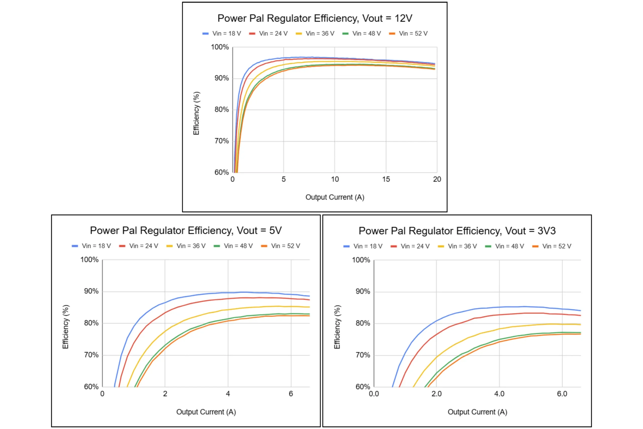
Regulator efficiency was characterized using a custom Python-based data collection script that interfaced with a bench power supply and a microcontroller calibrated as a two-channel voltmeter. In the absence of a programmable electronic load, the script guided manual load adjustments by prompting target currents and automatically logging voltage and current once the system stabilized. This approach reduced manual measurement effort by three times, making detailed efficiency sweeps across multiple input voltages practical without additional test equipment and significantly improving the sanity of the data collection process.
Power-up behavior and rail sequencing were captured directly using an oscilloscope. The measurements verify controlled startup of the primary input and downstream rails, demonstrating predictable sequencing and ramp behavior under real operating conditions.
Testing steady state thermals at the maximum power point
Testing was performed using electronic loads, oscilloscopes, and thermal monitoring. Here are examples of some of the testing that was completed:
Full Load Verification 12 V at 20 A continuous operation with 52V and 14V input, with inductors and MOSFETs monitored for thermal headroom. Although the main 12 V regulator is above 95% efficiency, at 12 A output that still means roughly 7.5 W of heat is dissipating from the power stage. This is maintained without an external fan. It can reach up to 12V 20A with external cooling at room temperature. 12V 16A while the 5V @ 6A and 3.3V at 6A thermal testing was also conducted but requires external cooling.
Transient Response Fast load steps applied to all three rails to evaluate undershoot, overshoot, and recovery time.
Ripple and Ringing Measurement Switch node and output rails probed to confirm low SW node spikes, output voltage ringing and acceptable ripple after layout improvements.
Surge and Protection Testing Reverse polarity protection, TVS clamping behavior, and UVLO thresholds validated at the full input voltage range.
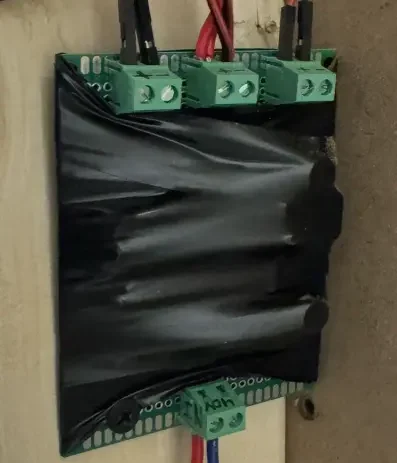
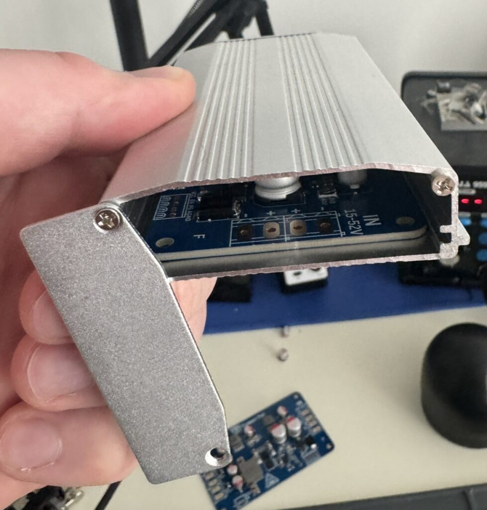
Waterproofing
The final revision required a complete redesign of the mechanical outline. The EMI shield footprint was removed, and the board was reshaped to fit inside a low cost extruded aluminum enclosure. This was changed because it could serve as the heatsink, the protective housing, and the EMI shield all at once. By coupling the high dissipation components to the enclosure walls, the thermal performance improved significantly while also giving the regulator a rugged, enclosed form factor suitable for outdoor deployments. The enclosure can be flooded with high temperature silicone to provide an IP67 rating with wires soldered directly to the input and output terminals and exposed outside. Custom metal end plates will be used to show useful product information.